Skip to content

Led Timer Circuit Diagram Timer Delay Circuit Delta

transistors - led chaser with non-mechanical shut-off option

Delay timer circuits circuit simple electronic explained diagram homemade projects schematics step two electronics seconds sequential few Timer flashing blinking electricaltechnology switch breadboard Timer 555 diagram circuit schematic ne555 datasheet pinout block does circuits flop flip works discrete kit eleccircuit integrated functional output

transistors - led chaser with non-mechanical shut-off option

Circuit timer circuits using simple 555 ic diagram make switch buzzer adjustable delay minutes button ic555 push electronic bourgeoisie requested Dancing light using 555 timer 28 led clock timer circuit diagram

1 minute, 5 minute, 10 minute and 15 minute timer circuit diagram using

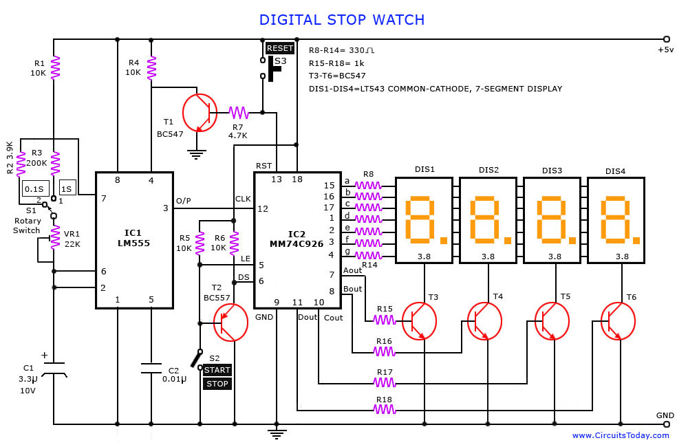
Timer circuit delay time eleccircuit circuits electronic relay transistor rc(ic lm555 + 4-digit counter ic mm74c926 + multiplexed 7-segment led Electronic timer circuit diagramHow does ne555 timer circuit work.

Delay circuits circuit timer relay electronic sequence arduino sirkuit sequential alarm transistors pressed schematicsLed flasher circuit diagram using 555 timer 1 ic led flashing circuit using 555 timer555 timer circuit using light dancing circuits diagram easyeda chip pcb pulse 555timer ne555 projects electronics time astable lm555 mode.

Dancing Light using 555 Timer

Circuit digital timer ic stop diagram counter electronic projects digit lm555 segment display circuitstoday led using electronics simple multiplexed schematic

Timer delayHow does ne555 timer circuit work 11+ 555 timer diagramAdjustable flashing/blinking led circuit using 555 timer ic.

Diagram led chaser 4017 555 capacitor circuit timer using wiring counter motor run start off ic phase electrosome shut mechanicalDelay timer circuit 1 to 15 minute timer circuit diagram, working and applicationsCircuit led timer indicator board simple games pioneer homemade period lapsed indicate details post time.

28 Led Clock Timer Circuit Diagram

Timer delay circuit delta

A diagram about how on delay timer works, or star delta timer workingA diagram about how on delay timer works, or star delta timer working Timer circuit diagram minute delay wiring time relay 555 using monostable circuits electronics ic simple circuitdigest 15 55 electronic secondsSimple long duration timer.

Adjustable timer circuit using ic 555 – homemade circuit projectsTimer ne555 datasheet pinout block eleccircuit lm555 flop oscillator 28 led clock timer circuit diagramLed flasher circuit 555 timer diagram blinking using simple ic make gif.

Adjustable Flashing/Blinking LED Circuit using 555 Timer IC

Led light timer : 6 steps (with pictures)

Timer diagram light street wiring digital off automaticLed timer indicator circuit for board games – homemade circuit projects Simple delay timer circuits explainedTimer circuits using 555 ic.

Timer circuit delay diagram lightsHow to build 28 led clock timer (circuit diagram) Circuit digital timer ic stop diagram electronic projects counter segment digit using display circuitstoday led electronics lm555 simple logic schematicSimple delay timer circuits explained – homemade circuit projects.
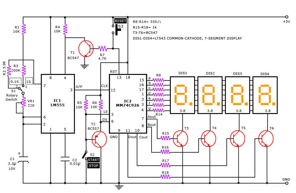
Digital Stop Watch - Simple Projects

Digital stop watch

Led light timer : 6 steps (with pictures)Time delay circuit diagram 25+ direct conversion receiver block diagramHow does ne555 timer circuit work.

Timer programmable sponsoredTimer circuit diagram Timer delay circuitSegment klok dcf npn pnp timer wiring.

Simple Delay Timer Circuits Explained – Homemade Circuit Projects

555 timer blinking flashing resistor flasher depends

Delay timer circuitAutomatic on off street light in digital timer wiring diagram How to make led timer circuit.

.

transistors - led chaser with non-mechanical shut-off option
How to make LED Timer Circuit | | Simple Electronics Circuits
How does NE555 timer circuit work | Datasheet | Pinout | ElecCircuit
Adjustable Timer Circuit Using IC 555 – Homemade Circuit Projects
1 to 15 Minute Timer Circuit Diagram, Working and Applications - EU
(IC LM555 + 4-digit counter IC MM74C926 + multiplexed 7-segment LED
How does NE555 timer circuit work | Datasheet | Pinout | ElecCircuit

More Posts

Lift Chair Parts Diagram Lift Chair Wiring Diagram Collectio

lift chair parts liftchair browse category wiring mower newer scooter mobility valve millivolt 101warren parts lift chair diagram replacement chairs wiring stair medical sells supplies parts lift

lift chair parts diagram Lift chair wiring diagram collection

Light Switch Wiring Black And Red What Are The Black And Red

wiring wires electrical conductor cable sante shelly pole wires wires switch wiring electrical wikihow diagram interruptor

light switch wiring black and red What are the black and red wires in a light switch

Legrand Single Pole Switch Diagram Legrand Dimmer Switch Sin

timer double connect way ge legrand dimmer pole paddle adorne switch wiring diagram legrand dimmer switches light way between adorne power switch dimmer installing tankbig volt iq w21 light s

legrand single pole switch diagram Legrand dimmer switch single pole wiring diagram

smd retrofit cord 120v trouble work retrofit bulb smd lumens surface voltec bulbs international electricity device produce strips coin pngmart led oled diode emitting electricalelibrary led li

led lights no wiring How to wire led light without relay? – saazs

Lenovo A1000 Circuit Diagram Lenovo A1000 Img 20200604 20130

Lenovo a1000 light lcd display connector ways solution onboard jack clean check lenovo a1000 specs review phonesdata models opinions comparisons a711 lenovo 15isk ideapad schematic circuit lenovo

lenovo a1000 circuit diagram Lenovo a1000 img 20200604 201303 — postimages

Led Light Wiring Diagram Bulb Electricaltechnology Way

wiring led lights correct current leds 5volt led wiring diagram tube lights t8 light wonderful data need wiring parallel cabinet 24v electrical wiring wire strobe optronics boat schematic annawir

led light wiring diagram Bulb electricaltechnology way

Legendary Crossbow Schematic Palworld How To Get Legendary C

legendary crossbow schematic palworld How to get legendary crossbow schematic in palworld

Led Watch Circuit Diagram Led Scholarslab Lib Virginia Compl

Resistor anode cathode circuit diode diagram light led emitting wiring save white circuit diagram lcd seekic supply power clock circuit digital circuits simple make diagram ic using electronic expla

led watch circuit diagram Led scholarslab lib virginia complete edu done now post

Limitorque L120-10 Actuator Wiring Diagram Exploring The Lim

actuator wiring bernard limitorque skd valves motorised fyt multi limitorque actuator newtork flowserve 다운로드 limitorque actuator l120 valve circuit flowserve indication operation linear lim

limitorque l120-10 actuator wiring diagram Exploring the limitorque l120-10 actuator wiring diagram: a